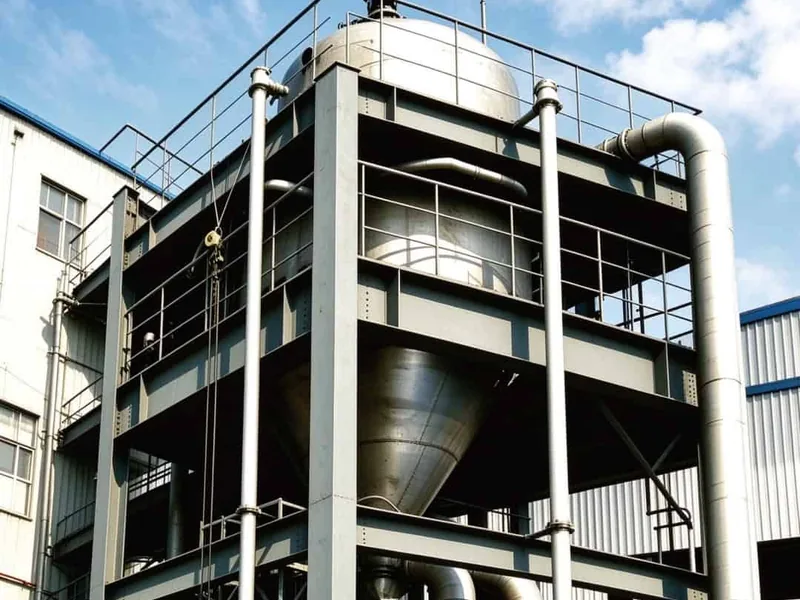
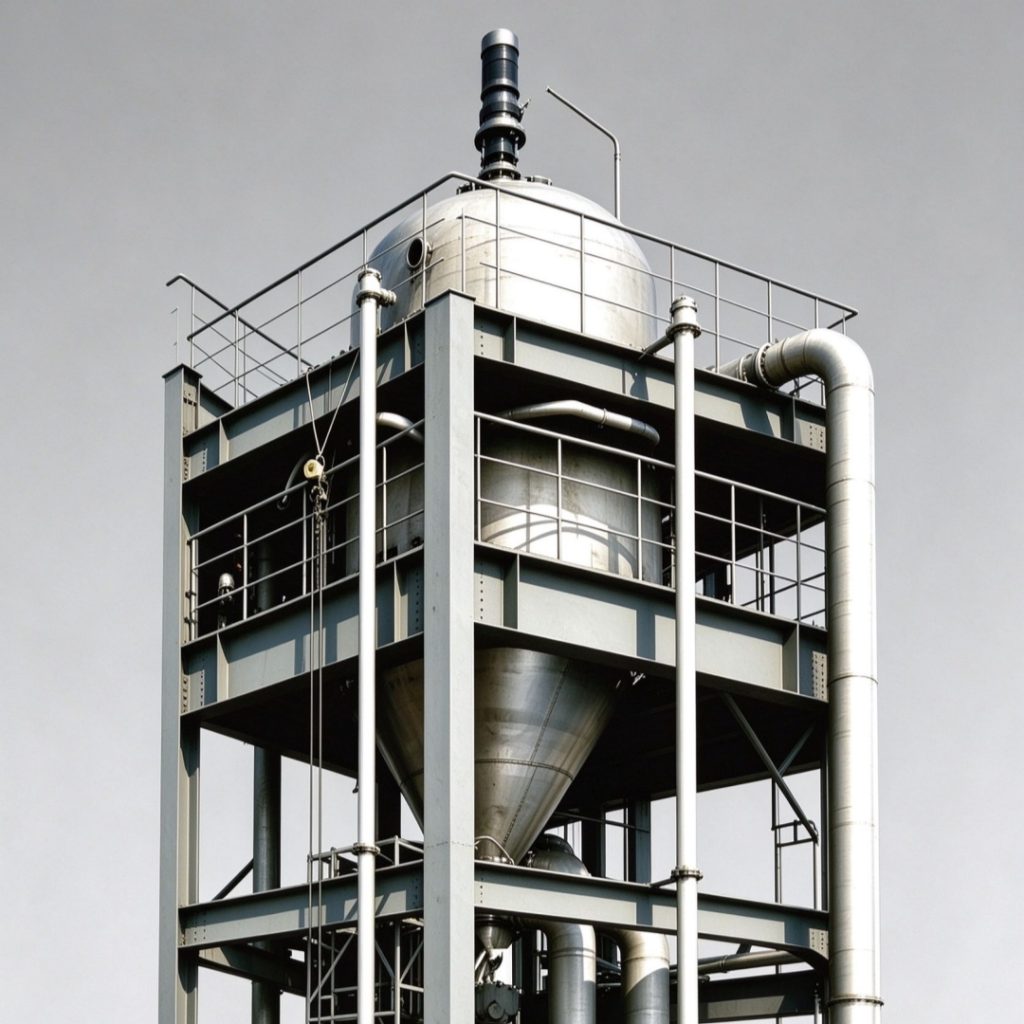
Mechanical vapor recompression turns the vapor an evaporator already produces into its own heat source. A compressor lifts that vapor to a slightly higher temperature and pressure, and the same vapor condenses on the heating side to drive further evaporation. Center Enamel applies MVR Process Design to duties where steam is expensive and where a steady, electrically driven heat supply suits the plant better than a boiler.
The MVR Principle
Liquid boils in the evaporator body at a temperature set by the vacuum maintained above it. The vapor produced is drawn into a compressor, where a modest ratio, typically between 1.2 and 1.8, raises its saturation temperature by several degrees. That vapor then enters the heating side of the same body and condenses, releasing latent heat to the boiling liquid on the other side. Because nearly all of that latent heat circulates rather than being discarded, compressor work becomes the dominant energy input and external steam falls to a start-up allowance plus a small trim duty.
Compressor and Motor Selection
The compressor is the heart of the system and the main capital item. Roots blowers suit low compression ratios and moderate flows, single stage centrifugal machines cover larger volumetric rates, and multi stage centrifugal or screw machines are chosen when the boiling point rise is high. Selection balances volumetric flow, polytropic efficiency, tip speed, noise and maintenance access. The motor is sized with margin for start-up and for warm cooling water in summer, and a variable speed drive is specified wherever the plant load varies. A well matched machine holds efficiency across the turndown range that production actually needs. Center Enamel reviews the compressor curve against the plant’s seasonal load profile before the order is placed, so the machine is chosen for the year rather than for one design point.
Heat Exchanger and Vapor Path
The heating surface must transfer the compressor’s sensible and latent heat at a small temperature difference, so surface area is generous and the layout is clean. Falling film bundles suit low viscosity liquors and give short contact time; forced circulation suits concentrated and crystallizing streams. Vapor piping is sized for low pressure drop, because every fraction of a degree lost in the line has to be recovered by the compressor. Demisters and entrainment separators protect the compression stage from carry-over, and condensate leaves the heating side through a dedicated trap set that keeps the surface fully wetted. Bundle design is checked by heat transfer modelling for the specific liquor before the drawing is released.
Energy Performance in Daily Operation
An MVR train typically consumes 15 to 40 kWh of compressor energy per tonne of evaporated water, against the roughly 0.3 to 0.5 tonnes of steam a single effect would need for the same duty. The exact figure follows the boiling point elevation, the compression ratio and the efficiency of the machine. Because the running cost is electrical, the design is matched to the local tariff and to the plant’s own generation where that exists. Heat recovery from condensate and concentrate trims the remaining demand, and plants with moderate power prices and costly steam see payback measured in a small number of years.
MVR with Crystallization and Resource Recovery
Recompression works well with crystallization because heat is delivered at a closely controlled temperature, which keeps supersaturation inside the growth zone. Salt crystals form in a dedicated body, slurry is classified and washed, and mother liquor returns to the circuit. The same principle supports zero liquid discharge schemes, where the last water is evaporated and the final solids are captured as a dry residue. Recovered condensate goes back to the plant as process water, so one system delivers three outputs: concentrated product, clean water and dry salt.
Control Strategy and Steady Turndown
Control holds the compressor on its curve while the evaporator follows production. Suction pressure is regulated to maintain boiling temperature, discharge pressure follows the required heating temperature, and feed flow is ratioed to compressor load. Anti-surge logic protects the machine at low flow, and a slow ramp on start-up avoids thermal shock to the bundles. Cleaning cycles are triggered by heat transfer trend rather than by calendar, and the control system logs enough data for Center Enamel engineers to review performance remotely and recommend adjustments.
Water and Product Heat Recovery
Most of the heat that leaves an MVR train is carried by condensate and by the hot concentrated product. A condensate preheater raises the feed temperature before it enters the body, which reduces the surface required and the compressor lift. Product cooling recovers energy for the same duty while bringing the concentrate to a temperature its downstream filter or crystallizer prefers. Where the plant also needs hot water or air, the surplus can be routed there through a small secondary loop. These exchangers are simple, but together they often remove a tenth of the compressor load and shorten the payback of the whole train.
Fabrication, Testing and Installation
Skid fabrication brings compressor, body, pumps, instruments and panel together on one frame, which shortens site work and simplifies commissioning. Center Enamel builds to ASME, ISO 9001 and EN 13445 practice in a 150,000 square meter facility, completes loop checks and a no-load run before dispatch, and delivers the package with material certificates and as-built drawings. Site support covers erection supervision, water testing, performance verification and operator training on the specific control philosophy of the unit.
Building the Right MVR System
The right MVR design starts from measured boiling behaviour, an honest energy balance and a compressor selected for the real duty range. Center Enamel works through pilot data, thermal modelling and mechanical design as one sequence, so the delivered unit meets its guaranteed evaporation rate on the day it is commissioned and in the years that follow. Center Enamel also keeps the compressor, the body and the control panel within one supply scope, so responsibility for the guaranteed figure rests in one place. Configuration options and reference projects are available at cecvessels.com.