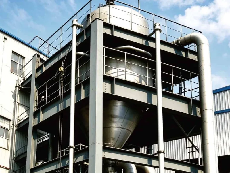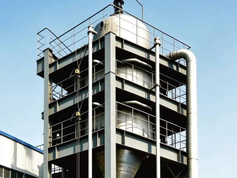
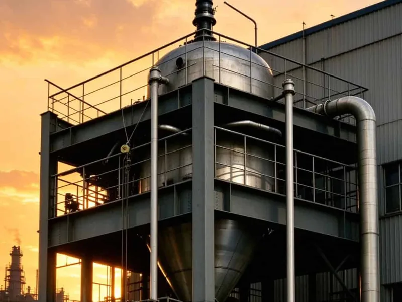
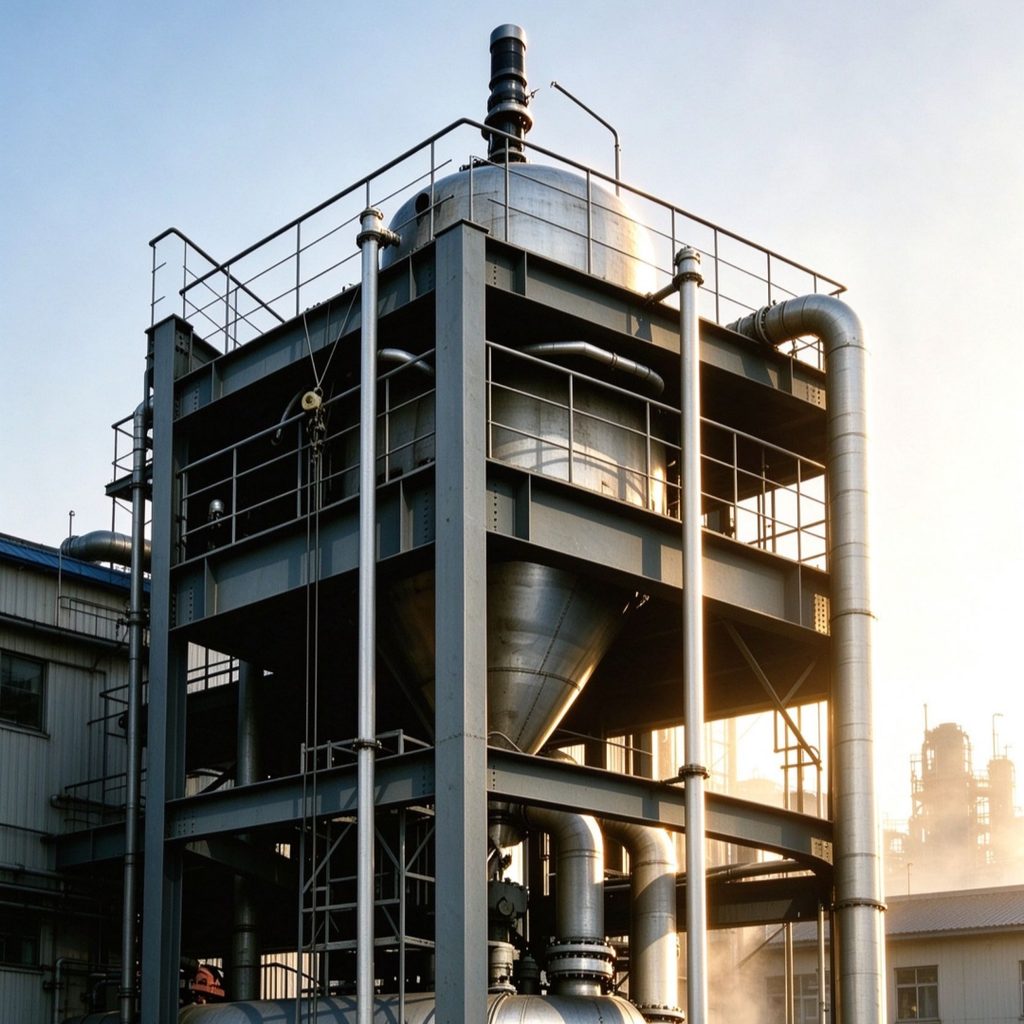
Continuous flow converts a sequence of batch steps into a steady production stream. Reagents are pumped at fixed ratios, mixed in line, held at a controlled temperature for a defined residence time, and separated downstream. A continuous flow process package brings these elements together as one tested unit, so the process behaves the same on the first day of production and in the fifth year.
What a Continuous Flow Process Package Includes
A complete package starts at the feed section, where tanks, pumps, and mass flow meters hold the reagent ratios. From there the stream passes through inline mixers, tubular reactors or coil loops, heat exchangers, and a residence section sized for the required reaction time, with sampling points between the stages. Each section carries its own instrument, so a change in one part of the line is visible before it reaches the next.
Downstream, the package may include phase separation, filtration, product collection, and solvent recovery. All of it sits on a steel skid with interconnecting pipework, a control cabinet, and utility connections, tested as a single system before dispatch so that site work is limited to setting the frame and tying in services.
Steady-State Behaviour and Process Stability
Flow processes reach a steady state in which every point in the line holds a constant composition and temperature. Stability therefore depends on tight control of flow ratio, zone temperature, and residence time, rather than on operator intervention during the batch, and small corrections at the pump are enough to hold the line. Where the reaction is fast, the mixer and the first coil sit close together to keep the mixing time short.
Start-up follows a defined order: purge with solvent, establish flow, bring each zone to temperature, then introduce the reagent stream. Loop checks at the factory confirm that instruments, valves, and the control sequence act as intended before the skid reaches site, and the same checks are repeated after utility connection.
Flow Path and Heat Management
Tube diameter, coil length, and mixer type are selected from the reaction kinetics and the allowable line resistance. Static mixers provide predictable blending without moving parts, while plate or shell heat exchangers hold each reaction zone at its set temperature and remove heat released by the reaction. The exchanger surface is sized from the heat release curve rather than from the nominal flow rate alone.
Jacket circuits, trace heating, and insulation keep the line isothermal between zones. Temperature sensors placed at the inlet and outlet of each section show the actual profile, which is the evidence operators need when a new recipe is transferred to the unit and when a deviation has to be traced to a specific section.
Materials, Seals, and Component Selection
Wetted materials follow the same compatibility review used for the laboratory route: stainless steel, alloys, and fluoropolymer components are matched to the solvent and reagent set. Gaskets, diaphragms, and valve seats are chosen from the same list, because the seal is usually the first item to limit a campaign. Spare gaskets and diaphragms are supplied for the components most likely to be replaced first.
Instrument selection follows the flow range and the required accuracy. Drain points and low-point valves are placed so the line can be emptied and rinsed between campaigns without dismantling pipework, and every dead volume is either avoided or made drainable.
Control Architecture and Production Data
A programmable controller runs the flow loops, temperature zones, and dosing ratios, while an operator screen shows the complete line at a glance. Recipes hold set points for each product, so a changeover is a matter of selecting the correct recipe and confirming the line has reached its new steady state.
Trends and batch records capture flow, temperature, and cumulative volume against time. That data supports quality release, process optimisation, and the reports that customers and auditors ask for, and it shows how quickly the line settled after a changeover.
Integration and Delivery by Center Enamel
Skid fabrication covers structural steel, pipe spooling, wiring, insulation, and instrument mounting. Factory acceptance testing runs the package on water or a safe simulant, which confirms pump curves, control response, and leak-free joints before shipment and gives the plant team a reference run for commissioning. The same test fluid and sequence are used again after installation, so the two sets of results can be compared directly. As a China continuous flow process package manufacturer, Center Enamel keeps the skid layout and the control design with one engineering team.
Documentation includes drawings, bills of material, material certificates, instrument lists, test records, and operating instructions. Center Enamel supports transport, site installation, and commissioning with engineers who worked on the package design and can answer questions about the layout without referring to a third party.
Scoping a Continuous Flow Project
Start with the reaction route, the required throughput, the residence time, and the utilities on site. A short trial on a pilot skid confirms mixing and heat transfer before the production package is released for fabrication, and the trial data becomes the basis for the control recipe.